ERMATIC® Solution
Installation, Operation, and Maintenance Instructions
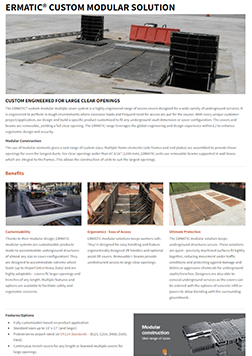
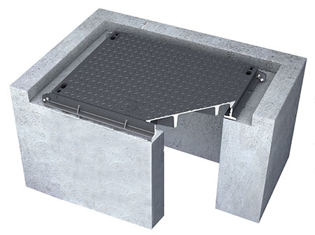
The ERMATIC® custom modular multiple cover system is a highly engineered range of access covers designed for a wide variety of underground services. The system is engineered to perform in tough environments where excessive loads and frequent need for access are required.
Instructions for installation, operation, and maintenance are below. Contact your local sales representative if you have questions or need further assistance.
Installation Operation Maintenance
Installation
Technical Assistance
EJ can provide, upon request, various levels of technical assistance for the installation of access covers and frames.
Objective
- Assist the contractor in the installation and grouting of the covers and frames.
- Help maintain the right factory controlled tolerances.
- Assist the contractor and end-user with practical operation, maintenance, and handling instructions.
- Contact your local EJ sales representative for more information.
Installation Recommendations
There is no standard or definitive guide to the installation of access covers and frames. These recommendations are designed to assist in the installation of ERMATIC covers in general situations that present no particular technical difficulties. All frames and beam wall boxes must be adequately, solidly, and continuously supported to a degree sufficient for the designed load conditions in each particular case. ERMATIC covers and frames are made from machined elements, assembled to strict tolerances.
The frames are assembled around their respective covers in order to provide continuous peripheral contact between the seatings and side contact faces. When correctly installed, the tight manufacturing controlled tolerances will be maintained, thus ensuring cover stability and non-rock and will prevent the ingress of debris and running rainwater (under normal rainwater conditions). In order to protect the machined surfaces from contamination with silt and mud, cover and frame components must be positioned or stored on clean surfaces.
Installation Recommended Steps
1. Foundation
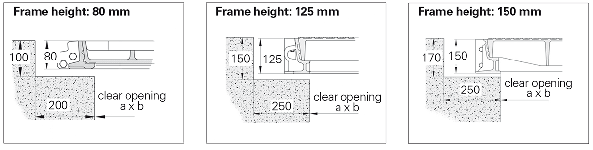
- For all covers and frames, prepare a peripheral foundation in accordance with the suggested dimensions (figure above).
- For removable beam assemblies and continuous duct assemblies, see the specific drawing details provided during the design or accompanying the delivery.
2. Installation and Forming
See the below tabs for series-specific instructions.
1/2/3 Part Covers and Frames Installation Recommendations
Installation and Forming
- Correctly center the cover and frame within the foundation.
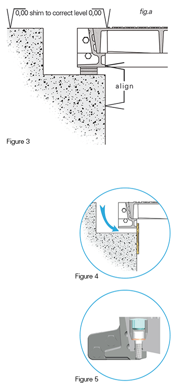
- In order to level the product to the correct road level, we strongly recommend the use of our optional level adjusting bolt kit. Otherwise, use shims and position those under each frame joint and add until you reach the desired level (Figure 3).
- Remove the cover(s) (for continuous duct do not remove all covers).
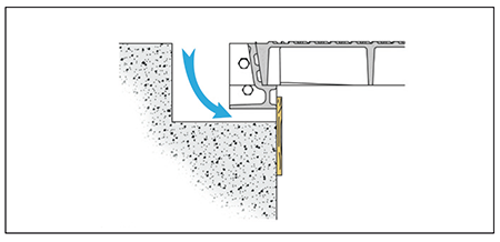
- Build form to close off the gap between the bottom of the frame and the concrete foundation of the chamber. Position form such that it is flush to I.D. of frame clear opening (Figure 4).
- Ensure the bottom of the frame will be fully supported with concrete.
- Check that the machined faces of the cover(s) and frame are free from dirt or debris. Clean if necessary.
- Replace the cover(s) and locking bolts.
- Tighten the locking bolts by successive steps in a diagonal pattern (Figure 5). A similar tightening torque must be applied on each bolt.
- Place plastic keyhole caps over keyholes.
3. Pouring
Important: The covers must be in their correct position(s) within the frame and bolted while the frames are poured in position.
- Vibrate the concrete to ensure it fills the void beneath the frame (see figure to the right).
- Finish concrete appropriately as required.
- If there is insufficient time to allow the concrete to fully cure before opening to traffic, use a rapid non-shrinking setting grout such as EMACO T926 or similar.
4. Reopening to Traffic
- Allow the grout and concrete to fully cure.
- Remove covers and remove all forming from interior of structure.
- Ensure contact faces of frames, covers, and seating areas are clean and free of debris.
- Remove debris and thoroughly clean bolt holes and keyholes.
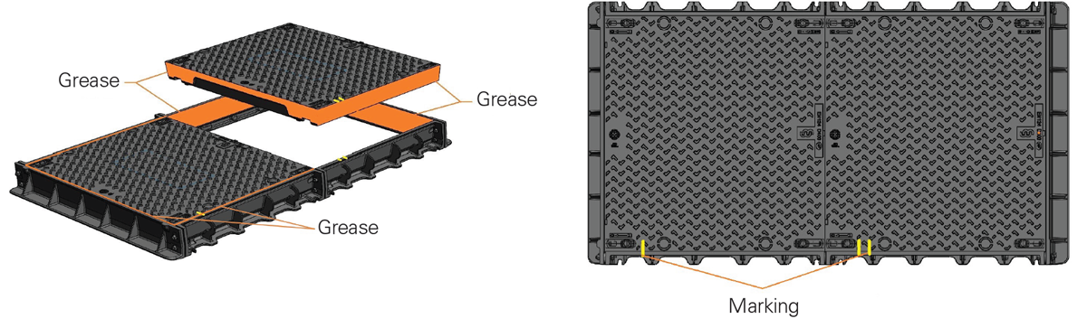
- Grease all contact faces and seating areas of frames and covers.
- For the grease: use recommended grease from Maintenance Instructions.
- Be careful not to contaminate the grease film with dust, sand, etc. Otherwise, repeat the cleaning and greasing procedure.
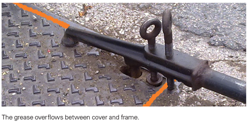
- Place the covers in the correct positions in the frame, noting the marking/position of the covers in the frame. The grease must overflow between cover and frame.
- Reinstall washers and locking bolts.
- The four bolts must be tightened by successive steps in a diagonal pattern. A similar tightening torque must be applied on each bolt.
- Reinstall the plastic keyhole caps.
Covers with Removable Beams Installation Recommendations
Installation and Forming
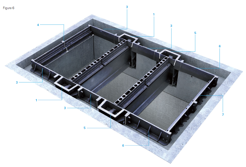
Start the assembly from one end of the chamber in accordance with the assembly drawing. Note the lettering on the beams and frame sections. All components must be positioned according to the assembly drawing.
(Each step number below corresponds to the numerals shown in Figure 6 above)
1. Install and correctly center the 1st beam (still bolted to the wall boxes) within the foundation.
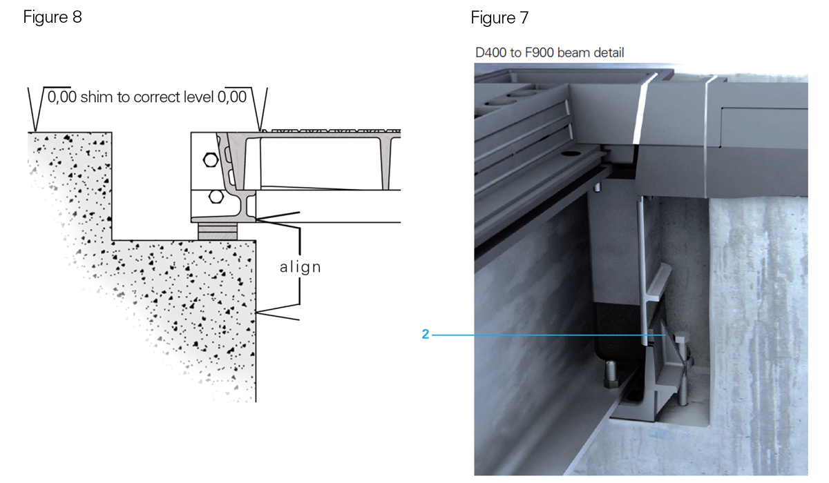
2. Correctly level the beam by adjusting the beam leveling bolts (Figure 7).
3. Install and bolt to the wall box the adjacent side frame sections (both sides).
4. Bolt the end frame sections (parallel to the beam) to the side frame sections.
5. Complete (if necessary) the installation of the next beams and frame elements by repeating the following 3 operations.
- Install and center correctly within the foundation, the 2nd, 3rd beam etc. (still bolted to the wall boxes).
- Correctly level the beam by adjusting the beam leveling bolts (Figure 7)
- Install and bolt to the wall box the adjacent side frame sections (both sides).
6. Finish and complete the construction of the frame by bolting the end frame sections (parallel to the beam), to the side frame sections.
7. Check to ensure that the frame assembly is centered within the chamber (Figure 8).
8. Shim to the correct level, (fig a) underneath each frame corner and underneath each frame joint using metal shims.
2.1
- Check that the machined contact faces the frame and covers are free from dust and mud. Clean if necessary.
- Position the covers in their respective frames. If applicable, refer to the assembly drawing.
- Check that the covers do not tilt and that they are in continuous contact within the frame. If necessary, adjust the shims and use pliers to obtain the correct condition.
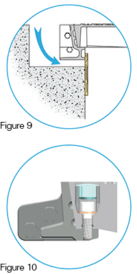
- Tighten the locking bolts by successive steps in a diagonal pattern (Figure 10). A similar tightening torque must be applied on each bolt.
- Ensure entire assembly is level and sqaure.
2.2
- Remove the cover(s).
- Build form to close off the gap between the bottom of the frame and the concrete foundation of the chamber. Position form such that it is flush to I.D. of frame clear opening (Figure 9).
- Form to perimeter of wall box ensuring that concrete does not fill interior cavity where beam is located.
- Ensure the bottom of the frame will be fully supported with concrete. (Also ensure that the underside of the wall box is fully supported with concrete.
- Check that the machined faces of the cover(s) and frame are free from dirt or debris. Clean if necessary.
- Replace the cover(s) and locking bolts.
- Tighten the locking bolts by successive steps in a diagonal pattern (figure 10). A similar tightening torque must be applied on each bolt.
- Ensure entire assembly remained level and square.
- Place plastic keyhole caps over keyholes.
3. Pouring
Important: The covers must be in their correct position(s) within the frame and bolted while the frames are poured in position.
- Vibrate the concrete to ensure it fills the void beneath the frame (see figure to the right).
- Finish concrete appropriately as required.
- If there is insufficient time to allow the concrete to fully cure before opening to traffic, use a rapid non-shrinking setting grout such as EMACO T926 or similar.
4. Reopening to Traffic
- Allow the grout and concrete to fully cure.
- Remove covers and remove all forming from interior of structure.
- Ensure contact faces of frames, covers, and seating areas are clean and free of debris.
- Remove debris and thoroughly clean bolt holes and keyholes.
- Grease all contact faces and seating areas of frames and covers.
- For the grease: use recommended grease from Maintenance Instructions.
- Be careful not to contaminate the grease film with dust, sand, etc. Otherwise, repeat the cleaning and greasing procedure.
- Place the covers in the correct positions in the frame, noting the marking/position of the covers in the frame. The grease must overflow between cover and frame.
- Reinstall washers and locking bolts.
- The four bolts must be tightened by successive steps in a diagonal pattern. A similar tightening torque must be applied on each bolt.
- Reinstall the plastic keyhole caps.
ERMATIC Beamed Unit Installation Video
Continuous Duct Covers and Frames Installation Recommendations
Installation and Forming
Duct covers and frames are usually shipped in "pre-assembled" modules (or elements).
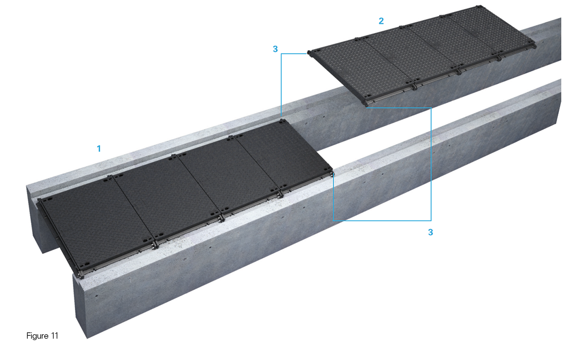
- Position the first module 1 in the foundation in accordance with the assembly drawing (Figure 11).
- Do not cut the metal bands connecting the covers with the frames.
- Center the duct assembly within the clear opening of the duct chamber.
- In order to level the product to the correct road level, we strongly recommend the use of our optional level adjusting bolt kit.
- Otherwise, use metal shims; position those under each frame joint and add until you reach the desired level.
- Position the second module 2 in the foundation.
- Repeat the above section on centering and level adjusting.
- Bolt the second module to the first one 3.
- Complete the installation by repeating the previous instructions and proceed module by module.
- Finish the installation with the instructions from the 1/2/3 part ERMATIC recommendations, after removal of metal bands and covers (if applicable).
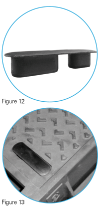
- Mask the keyways with the plastic plugs (Figure 12 and Figure 13). And, if applicable, fit the oval plastic plugs in the bottom of the covers (recessed covers only).
3. Pouring
Important: The covers must be in their correct position(s) within the frame and bolted while the frames are poured in position.
- Vibrate the concrete to ensure it fills the void beneath the frame (see figure to the right).
- Finish concrete appropriately as required.
- If there is insufficient time to allow the concrete to fully cure before opening to traffic, use a rapid non-shrinking setting grout such as EMACO T926 or similar.
4. Reopening to Traffic
- Allow the grout and concrete to fully cure.
- Remove covers and remove all forming from interior of structure.
- Ensure contact faces of frames, covers, and seating areas are clean and free of debris.
- Remove debris and thoroughly clean bolt holes and keyholes.
- Grease all contact faces and seating areas of frames and covers.
- For the grease: use recommended grease from Maintenance Instructions.
- Be careful not to contaminate the grease film with dust, sand, etc. Otherwise, repeat the cleaning and greasing procedure.
- Place the covers in the correct positions in the frame, noting the marking/position of the covers in the frame. The grease must overflow between cover and frame.
- Reinstall washers and locking bolts.
- The four bolts must be tightened by successive steps in a diagonal pattern. A similar tightening torque must be applied on each bolt.
- Reinstall the plastic keyhole caps.
ERMATIC Continuous Duct Covers Installation Video
Recessed Covers for Concrete Infill Installation Recommendations
These recommendations are given as guidelines only and reflect the latest research available to us; nevertheless, we cannot accept any liability from their application. The description and choice of materials must be appropriate to the specific conditions of each application (conditions of use and installation). The concrete infill is part of the complete product, so particular care should be taken regarding its manufacture and application.
The expected quality shall be the same as required for construction work concrete with high mechanical performances (> 40 Mpa after 28 days on a test cylinder of 150 x 300 mm). Therefore, its composition should be analyzed to achieve the highest possible performance with regard to the specific concreting conditions of your application.
a. Support
The recesses must be clean, exempt from any trace of products such as grease, oil, sand, dust. Any non adhesive particles must be removed.
b. Composition of the Concrete
As an indication, the typical concrete mix design may be characterized by :
Cement
- A cement CEM I or II 52,2 proportion near to 450 kg/m3.
- Its chemical composition shall be adapted to the area of installation, e.g. cement type PM (marine and chloride environments) for works exposed to a sea atmosphere.
Granules
- A G/S (gravel / sand) ratio < 1,5.
- The diameter of the biggest granule shall be < 12,5 mm.
- The required acceptance criteria must be those of construction work concrete, of which the characterized resistance after 28 days is over 40 Mpa.
- If the granule(s) is (are) classified as potentially reactive (PR), then the total rate of active alkalines in the concrete must be limited to a maximum of 3 kg/m3 (this requirement will often lead to the choice of low alkali cement (< 0,6 %)
Water
- The ratio of water / cement (W/C) must be smaller than 0,4.
- The water used must be drinking water.
Admixtures
In order to reduce the W/C ratio and with respect to the maintenance of the rheology for the time necessary to fill the several covers with concrete of the same batch, admixtures must be certified to the NF Mark or comply with national standards (BS/ASTM/AFNOR ...), such as plasticisers, High Range Water Reducers, set retarding admixtures. The dosage of these products (expressed as a percentage of the cement weight) must be kept inside the limits defined by the supplier or in the product technical information sheet, in order to avoid detrimental effects on the other properties of concrete.
c. Installation
Temperature of the concrete at the time of delivery : between 10 and 32°C.
Temperature of the concrete appliances:
- Except for special circumstances, concreting must not be carried out on appliances:
- Which temperature is < 5°C, or
- Which temperature varies by more than 10°C from the temperature of the concrete.
Vibrating :
- After filling, the concrete must be vibrated, preferably on a vibration table. In case of vibration needles (pervibrators), the picking must be done regularly on the cover surface while avoiding any contact with the cast iron.
- The vibration should obtain a maximum compacity and a perfect filling of the recesses, without causing any segregation.
Finishing :
- The filling must be carried out without excess
- A level surface must be assured and checked by means of a straightedge. The maximum fluctuation allowed is 3 mm.
- The obtained surface must be equivalent to that of the carriageway level.
d. Curing of Concrete
Immediately after manufacturing and cuffing the free surface, the latter must be protected from the free circulation of air and from any evaporation/desiccation.
This can be achieved :
- Either by storing the covers in a place where the atmosphere has a humidity ratio near to 95 %.
- Either by pulverizing it with a curing compound of which the efficiency has been proved (re. list of approval and reference for the execution of carriageways or airfield pavements in concrete). In case of concreting at low temperatures, every precaution must be taken to make sure that the temperature of the concrete remains above 5°C.
e. Release
The works must only be released when the resistance of the concrete infill will have attained 40MPa.
Reopening to Traffic
- Allow the grout and concrete to fully cure.
- Remove covers and remove all forming from interior of structure.
- Ensure contact faces of frames, covers, and seating areas are clean and free of debris.
- Remove debris and thoroughly clean bolt holes and keyholes.
- Grease all contact faces and seating areas of frames and covers.
- For the grease: use recommended grease from Maintenance Instructions.
- Be careful not to contaminate the grease film with dust, sand, etc. Otherwise, repeat the cleaning and greasing procedure.
- Place the covers in the correct positions in the frame, noting the marking/position of the covers in the frame. The grease must overflow between cover and frame.
- Reinstall washers and locking bolts.
- The four bolts must be tightened by successive steps in a diagonal pattern. A similar tightening torque must be applied on each bolt.
- Reinstall the plastic keyhole caps.
Technical assistance/Other information
If you require any further information, please contact your local EJ sales representative.
1/2/3 Part Covers and Frames Installation Recommendations
Installation and Forming
- Correctly center the cover and frame within the foundation.
- In order to level the product to the correct road level, we strongly recommend the use of our optional level adjusting bolt kit. Otherwise, use shims and position those under each frame joint and add until you reach the desired level (Figure 3).
- Remove the cover(s) (for continuous duct do not remove all covers).
- Build form to close off the gap between the bottom of the frame and the concrete foundation of the chamber. Position form such that it is flush to I.D. of frame clear opening (Figure 4).
- Ensure the bottom of the frame will be fully supported with concrete.
- Check that the machined faces of the cover(s) and frame are free from dirt or debris. Clean if necessary.
- Replace the cover(s) and locking bolts.
- Tighten the locking bolts by successive steps in a diagonal pattern (Figure 5). A similar tightening torque must be applied on each bolt.
- Place plastic keyhole caps over keyholes.
3. Pouring
Important: The covers must be in their correct position(s) within the frame and bolted while the frames are poured in position.
- Vibrate the concrete to ensure it fills the void beneath the frame (see figure to the right).
- Finish concrete appropriately as required.
- If there is insufficient time to allow the concrete to fully cure before opening to traffic, use a rapid non-shrinking setting grout such as EMACO T926 or similar.
4. Reopening to Traffic
- Allow the grout and concrete to fully cure.
- Remove covers and remove all forming from interior of structure.
- Ensure contact faces of frames, covers, and seating areas are clean and free of debris.
- Remove debris and thoroughly clean bolt holes and keyholes.
- Grease all contact faces and seating areas of frames and covers.
- For the grease: use recommended grease from Maintenance Instructions.
- Be careful not to contaminate the grease film with dust, sand, etc. Otherwise, repeat the cleaning and greasing procedure.
- Place the covers in the correct positions in the frame, noting the marking/position of the covers in the frame. The grease must overflow between cover and frame.
- Reinstall washers and locking bolts.
- The four bolts must be tightened by successive steps in a diagonal pattern. A similar tightening torque must be applied on each bolt.
- Reinstall the plastic keyhole caps.
Covers with Removable Beams Installation Recommendations
Installation and Forming
Start the assembly from one end of the chamber in accordance with the assembly drawing. Note the lettering on the beams and frame sections. All components must be positioned according to the assembly drawing.
(Each step number below corresponds to the numerals shown in Figure 6 above)
1. Install and correctly center the 1st beam (still bolted to the wall boxes) within the foundation.
2. Correctly level the beam by adjusting the beam leveling bolts (Figure 7).
3. Install and bolt to the wall box the adjacent side frame sections (both sides).
4. Bolt the end frame sections (parallel to the beam) to the side frame sections.
5. Complete (if necessary) the installation of the next beams and frame elements by repeating the following 3 operations.
- Install and center correctly within the foundation, the 2nd, 3rd beam etc. (still bolted to the wall boxes).
- Correctly level the beam by adjusting the beam leveling bolts (Figure 7)
- Install and bolt to the wall box the adjacent side frame sections (both sides).
6. Finish and complete the construction of the frame by bolting the end frame sections (parallel to the beam), to the side frame sections.
7. Check to ensure that the frame assembly is centered within the chamber (Figure 8).
8. Shim to the correct level, (fig a) underneath each frame corner and underneath each frame joint using metal shims.
2.1
- Check that the machined contact faces the frame and covers are free from dust and mud. Clean if necessary.
- Position the covers in their respective frames. If applicable, refer to the assembly drawing.
- Check that the covers do not tilt and that they are in continuous contact within the frame. If necessary, adjust the shims and use pliers to obtain the correct condition.
- Tighten the locking bolts by successive steps in a diagonal pattern (Figure 10). A similar tightening torque must be applied on each bolt.
- Ensure entire assembly is level and sqaure.
2.2
- Remove the cover(s).
- Build form to close off the gap between the bottom of the frame and the concrete foundation of the chamber. Position form such that it is flush to I.D. of frame clear opening (Figure 9).
- Form to perimeter of wall box ensuring that concrete does not fill interior cavity where beam is located.
- Ensure the bottom of the frame will be fully supported with concrete. (Also ensure that the underside of the wall box is fully supported with concrete.
- Check that the machined faces of the cover(s) and frame are free from dirt or debris. Clean if necessary.
- Replace the cover(s) and locking bolts.
- Tighten the locking bolts by successive steps in a diagonal pattern (figure 10). A similar tightening torque must be applied on each bolt.
- Ensure entire assembly remained level and square.
- Place plastic keyhole caps over keyholes.
3. Pouring
Important: The covers must be in their correct position(s) within the frame and bolted while the frames are poured in position.
- Vibrate the concrete to ensure it fills the void beneath the frame (see figure to the right).
- Finish concrete appropriately as required.
- If there is insufficient time to allow the concrete to fully cure before opening to traffic, use a rapid non-shrinking setting grout such as EMACO T926 or similar.
4. Reopening to Traffic
- Allow the grout and concrete to fully cure.
- Remove covers and remove all forming from interior of structure.
- Ensure contact faces of frames, covers, and seating areas are clean and free of debris.
- Remove debris and thoroughly clean bolt holes and keyholes.
- Grease all contact faces and seating areas of frames and covers.
- For the grease: use recommended grease from Maintenance Instructions.
- Be careful not to contaminate the grease film with dust, sand, etc. Otherwise, repeat the cleaning and greasing procedure.
- Place the covers in the correct positions in the frame, noting the marking/position of the covers in the frame. The grease must overflow between cover and frame.
- Reinstall washers and locking bolts.
- The four bolts must be tightened by successive steps in a diagonal pattern. A similar tightening torque must be applied on each bolt.
- Reinstall the plastic keyhole caps.
ERMATIC Beamed Unit Installation Video
Continuous Duct Covers and Frames Installation Recommendations
Installation and Forming
Duct covers and frames are usually shipped in "pre-assembled" modules (or elements).
- Position the first module 1 in the foundation in accordance with the assembly drawing (Figure 11).
- Do not cut the metal bands connecting the covers with the frames.
- Center the duct assembly within the clear opening of the duct chamber.
- In order to level the product to the correct road level, we strongly recommend the use of our optional level adjusting bolt kit.
- Otherwise, use metal shims; position those under each frame joint and add until you reach the desired level.
- Position the second module 2 in the foundation.
- Repeat the above section on centering and level adjusting.
- Bolt the second module to the first one 3.
- Complete the installation by repeating the previous instructions and proceed module by module.
- Finish the installation with the instructions from the 1/2/3 part ERMATIC recommendations, after removal of metal bands and covers (if applicable).
- Mask the keyways with the plastic plugs (Figure 12 and Figure 13). And, if applicable, fit the oval plastic plugs in the bottom of the covers (recessed covers only).
3. Pouring
Important: The covers must be in their correct position(s) within the frame and bolted while the frames are poured in position.
- Vibrate the concrete to ensure it fills the void beneath the frame (see figure to the right).
- Finish concrete appropriately as required.
- If there is insufficient time to allow the concrete to fully cure before opening to traffic, use a rapid non-shrinking setting grout such as EMACO T926 or similar.
4. Reopening to Traffic
- Allow the grout and concrete to fully cure.
- Remove covers and remove all forming from interior of structure.
- Ensure contact faces of frames, covers, and seating areas are clean and free of debris.
- Remove debris and thoroughly clean bolt holes and keyholes.
- Grease all contact faces and seating areas of frames and covers.
- For the grease: use recommended grease from Maintenance Instructions.
- Be careful not to contaminate the grease film with dust, sand, etc. Otherwise, repeat the cleaning and greasing procedure.
- Place the covers in the correct positions in the frame, noting the marking/position of the covers in the frame. The grease must overflow between cover and frame.
- Reinstall washers and locking bolts.
- The four bolts must be tightened by successive steps in a diagonal pattern. A similar tightening torque must be applied on each bolt.
- Reinstall the plastic keyhole caps.
ERMATIC Continuous Duct Covers Installation Video
Recessed Covers for Concrete Infill Installation Recommendations
These recommendations are given as guidelines only and reflect the latest research available to us; nevertheless, we cannot accept any liability from their application. The description and choice of materials must be appropriate to the specific conditions of each application (conditions of use and installation). The concrete infill is part of the complete product, so particular care should be taken regarding its manufacture and application.
The expected quality shall be the same as required for construction work concrete with high mechanical performances (> 40 Mpa after 28 days on a test cylinder of 150 x 300 mm). Therefore, its composition should be analyzed to achieve the highest possible performance with regard to the specific concreting conditions of your application.
a. Support
The recesses must be clean, exempt from any trace of products such as grease, oil, sand, dust. Any non adhesive particles must be removed.
b. Composition of the Concrete
As an indication, the typical concrete mix design may be characterized by :
Cement
- A cement CEM I or II 52,2 proportion near to 450 kg/m3.
- Its chemical composition shall be adapted to the area of installation, e.g. cement type PM (marine and chloride environments) for works exposed to a sea atmosphere.
Granules
- A G/S (gravel / sand) ratio < 1,5.
- The diameter of the biggest granule shall be < 12,5 mm.
- The required acceptance criteria must be those of construction work concrete, of which the characterized resistance after 28 days is over 40 Mpa.
- If the granule(s) is (are) classified as potentially reactive (PR), then the total rate of active alkalines in the concrete must be limited to a maximum of 3 kg/m3 (this requirement will often lead to the choice of low alkali cement (< 0,6 %)
Water
- The ratio of water / cement (W/C) must be smaller than 0,4.
- The water used must be drinking water.
Admixtures
In order to reduce the W/C ratio and with respect to the maintenance of the rheology for the time necessary to fill the several covers with concrete of the same batch, admixtures must be certified to the NF Mark or comply with national standards (BS/ASTM/AFNOR ...), such as plasticisers, High Range Water Reducers, set retarding admixtures. The dosage of these products (expressed as a percentage of the cement weight) must be kept inside the limits defined by the supplier or in the product technical information sheet, in order to avoid detrimental effects on the other properties of concrete.
c. Installation
Temperature of the concrete at the time of delivery : between 10 and 32°C.
Temperature of the concrete appliances:
- Except for special circumstances, concreting must not be carried out on appliances:
- Which temperature is < 5°C, or
- Which temperature varies by more than 10°C from the temperature of the concrete.
Vibrating :
- After filling, the concrete must be vibrated, preferably on a vibration table. In case of vibration needles (pervibrators), the picking must be done regularly on the cover surface while avoiding any contact with the cast iron.
- The vibration should obtain a maximum compacity and a perfect filling of the recesses, without causing any segregation.
Finishing :
- The filling must be carried out without excess
- A level surface must be assured and checked by means of a straightedge. The maximum fluctuation allowed is 3 mm.
- The obtained surface must be equivalent to that of the carriageway level.
d. Curing of Concrete
Immediately after manufacturing and cuffing the free surface, the latter must be protected from the free circulation of air and from any evaporation/desiccation.
This can be achieved :
- Either by storing the covers in a place where the atmosphere has a humidity ratio near to 95 %.
- Either by pulverizing it with a curing compound of which the efficiency has been proved (re. list of approval and reference for the execution of carriageways or airfield pavements in concrete). In case of concreting at low temperatures, every precaution must be taken to make sure that the temperature of the concrete remains above 5°C.
e. Release
The works must only be released when the resistance of the concrete infill will have attained 40MPa.
Reopening to Traffic
- Allow the grout and concrete to fully cure.
- Remove covers and remove all forming from interior of structure.
- Ensure contact faces of frames, covers, and seating areas are clean and free of debris.
- Remove debris and thoroughly clean bolt holes and keyholes.
- Grease all contact faces and seating areas of frames and covers.
- For the grease: use recommended grease from Maintenance Instructions.
- Be careful not to contaminate the grease film with dust, sand, etc. Otherwise, repeat the cleaning and greasing procedure.
- Place the covers in the correct positions in the frame, noting the marking/position of the covers in the frame. The grease must overflow between cover and frame.
- Reinstall washers and locking bolts.
- The four bolts must be tightened by successive steps in a diagonal pattern. A similar tightening torque must be applied on each bolt.
- Reinstall the plastic keyhole caps.
Technical assistance/Other information
If you require any further information, please contact your local EJ sales representative.
BACK TO TOP

Operation
Take all usual precautions when working on roadway/footway opened products.
- Operators should wear appropriate PPE: Safety glasses, helmet, safety gloves, safety vest, safety shoes
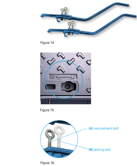
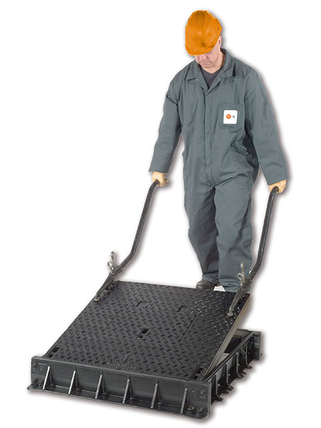
- For handling, use a pair of EM keys (Figure 14) with blocking and jacking bolts, designed for safety and ergonomics when removing and replacing covers.
- Additional tools that may be required: 10, 12, or 14 hex/allen key, screwdriver. Special OTC key if covers are equipped with OTC security bolting.
Important Details to Note:
- Covers can only be opened in one direction, as indicated by an arrow as shown in Figure 15.
- Note the position of each cover in the frame; these are not interchangeable. Ensure that corresponding stamped letters are visible on both covers and frame sections.
- Use of impact wrench not recommended.
Opening:
- Remove the plastic keyhole caps and locking bolts.
- Clean the keyway openings with a screw driver or appropriate tool.
- Completely insert the EM keys into the keyways that have the open
arrow marked beside them (Two keys per cover) - Tighten the securement bolt (A; Figure 16) by hand to lock the key in
position. Do not over tighten, as this may damage the key.
- Tighten the jacking bolt (B; Figure 16) to help release cover from fully
seated position.
- Once the cover is loose, lift the leading edge and pull the cover from
the frame along the greased machined seatings. - Use EM keys to slide cover to a safe location to ensure adequate
access to opening and room for removal of additional covers, if
necessary.
Closing:
- Clean and grease the machined faces of the cover and frame (see maintenance section)
- Unscrew the jacking bolt on the EM key so that it is not in the way during the operation. (B; Figure 16)
- Position the covers in place, noting the marking system visibly stamped into each cover and frame.
- Replace washers and locking bolts. Ensure bolts engage threads on frame.
- The four bolts must be tightened by successive steps in the diagonal pattern. A similar tightening torque must be applied on each bolt.
- Replace the plastic keyhole caps.
ERMATIC Operation Demonstration Video
ERMATIC Opening and Closing
BACK TO TOP
Maintenance
Please consult our commercial department for assistance.
Maintenance procedure: Use of impact wrench not recommended.
Maintenance procedures must be carried out each time the cover is opened and as required by environmental conditions.
Please follow all relevant practices associated with working around open manholes and vaults.
Operators should wear appropriate PPE: Safety glasses, helmet, safety gloves, safety vest, and safety shoes.
Before opening the product, note the position of each cover in the frame; these are not interchangeable. Ensure that corresponding stamped letters are visible on both covers and frame sections.
Tools/Equipment:
- Screwdriver
- Compressed air
- Allen key (12mm) or OTC key depending on locking bolt.
- Set of ERMATIC keys. (Product code 502402 or NR532752)
- Brush and putty knife/scraper (to apply grease)
- Total Grease "Multis ep2" or similar applied by brush or putty knife
- Use existing or new washers if necessary. Contact EJ if replacement is required.
To do:
- Remove plastic caps.
- Clean keyholes.
- Unscrew and remove bolts and washers.
- Lift out the cover using the EM keys.
- Scrape and wipe all grease and contaminants from the vertical and horizontal machined surfaces of the cover and frame.
- Remove debris and thoroughly clean bolt holes and keyholes.
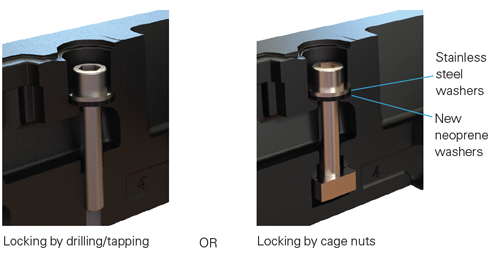
- Clean the cage nuts and, if necessary, replace them and the neoprene washers. If products are drilled and tapped, clean the threads to 20mm depth.
- Grease abundantly all vertical and horizontal machined surfaces of cover and frame.
- Be careful not to contaminate the grease film with dust, sand, etc. Otherwise, repeat the cleaning and greasing procedure.
- Place the cover in the correct position in the frame, noting the marking/position of the covers in the frame. The grease must overflow between cover and frame.
- Replace washers and locking bolts.
- The four bolts must be tightened by successive steps in a diagonal pattern. A similar tightening torque must be applied on each screw.
- Replace the plastic keyhole caps.
ERMATIC Grease Application